2021. 8. 9. 05:12ㆍ그래픽스/vk
Fixed functions
- 이전 그래픽 API는 그래픽 파이프라인의 대부분의 단계에 대해 기본 상태를 제공했음
- 하지만 Vulkan에서는 뷰포트 크기와 색상 혼합 등과 같은 모든것에 대해 명시적이어야함.
- 이 장에서는 이런 fixed function operations에 대해 다룰것.
1. Vertex input
- VkPipelineVertexInputStateCreateInfo 구조체를 기술해야함
- vertex shader로 넘길 vertex data의 format을 기술해야한다.
- 대략 두가지를 기술해야함.
- Bindings: spacing between data and whether the data is per-vertex or per-instance (see instancing)
- Attribute descriptions: type of the attributes passed to the vertex shader, which binding to load them from and at which offset
- 앞에서 쉐이더에 하드코딩했기 때문에 현재 로드할 버텍스 데이터가 없음을 지정해야함
- 이에 대해선 vertex buffer에서 다시 살펴봄
VkPipelineVertexInputStateCreateInfo vertexInputInfo{};
vertexInputInfo.sType = VK_STRUCTURE_TYPE_PIPELINE_VERTEX_INPUT_STATE_CREATE_INFO;
vertexInputInfo.vertexBindingDescriptionCount = 0;
vertexInputInfo.pVertexBindingDescriptions = nullptr; // Optional
vertexInputInfo.vertexAttributeDescriptionCount = 0;
vertexInputInfo.pVertexAttributeDescriptions = nullptr; // Optional
-pVertexBindingDescriptions , pVertexAttributeDescriptions : 위에서 언급한 로드할 vertex data를 구체적으로 기술하는 구조체 배열를 추가해야함
- createGraphicsPipeline에서 shaderStages 배열 바로 뒤에 와야한다.
2. Input assembly
- VkPipelineInputAssemblyStateCreateInfo 구조체 또한 두가지를 기술해야함
- 어떤 종류의 geometry 가 vertices로부터 그려지는지.
- primitive가 다시 시작했는지에 대한 여부 (특별한 인덱스 값으로 다시시작)
- - - - Primitive restart is not allowed for “list” topologies.
- - - - controls whether a special vertex index value is treated as restarting the assembly of primitives.
- - - - This enable only applies to indexed draws
- - - - strip과 fan을 특별한 인덱스를 통해 분리
- - - - 여러개의 연결되어 있지 않은 primitive를 한번의 drawcall로 렌더링?
- - - - index list에 special index를 추가해서 그 부분부터 primitive를 새로 그리는것
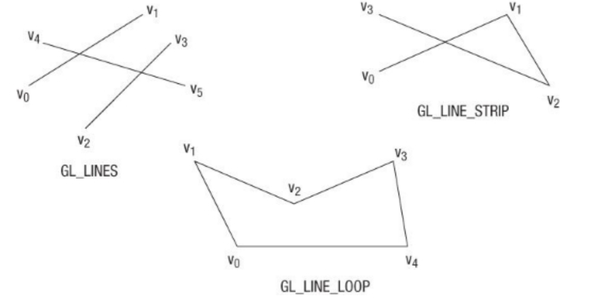
- 전자는 topology 멤버로 기술하며, 다음과 같은 값을 가질 수 있음
- VK_PRIMITIVE_TOPOLOGY_POINT_LIST: vertices의 포인트 리스트 ( 점을 생성)
- VK_PRIMITIVE_TOPOLOGY_LINE_LIST: 재사용하지 않는 두개의 정점으로 선을 그림 (vertex를 쌍으로 묶음)
- VK_PRIMITIVE_TOPOLOGY_LINE_STRIP: 선을 그릴때 마지막 정점이 시작정점이되어 연속적인 선을 그림
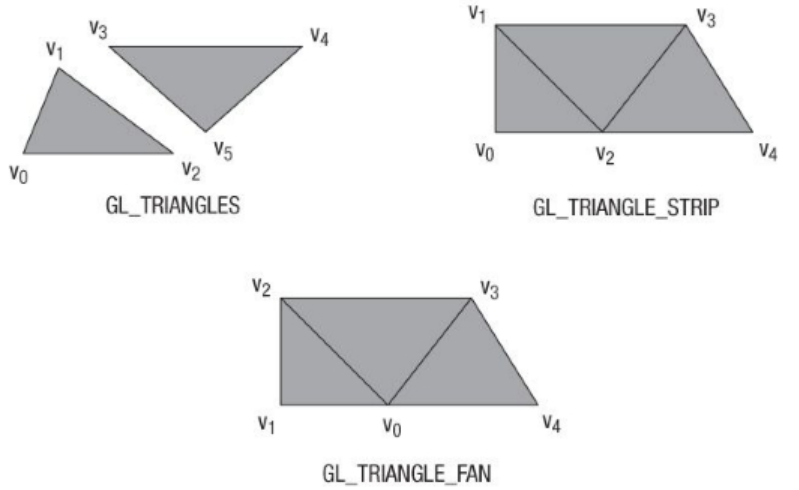
- VK_PRIMITIVE_TOPOLOGY_TRIANGLE_LIST: 모든 정점이 3개씩 묶여, 분리된 삼각형을 형성
- VK_PRIMITIVE_TOPOLOGY_TRIANGLE_STRIP: 첫 세 정점을 삼각형으로 만든 뒤, 마지막 두 정점과 새로운 정점으로 연속적으로 삼각형을 그림.
- VK_PRIMITIVE_TOPOLOGY_TRIANGLE_FAN: 첫 세 정점으로 삼각형으로 만든뒤, 중간 정점을 빼고 새로운 정점을 추가하여 연속적으로 삼각형을 그림
- 보통, 정점은 인덱스에 의해 순차적으로 vertexbuffer에서 로드되지만
- element buffer 를 사용하면 자체적인 indices를 사용할 수 있음
- 이를 통해 정점 재사용과 같은 최적화를 수행할 수 있다. (draw call을 줄일 수 있어 성능상 유리)
- primitiveRestartEnable 멤버를 VK_TRUE로 설정하면
- 특수 인덱스 0xFFFF or 0xFFFFFFFF 를 사용하여
- _STRIP topology모드에서 선과 삼각형 이 아닌것을 그릴 수 있음.
- tutorial에서는 삼각형만을 목표로 하므로, 다음과 같이 설정함.
VkPipelineInputAssemblyStateCreateInfo inputAssembly{};
inputAssembly.sType = VK_STRUCTURE_TYPE_PIPELINE_INPUT_ASSEMBLY_STATE_CREATE_INFO;
inputAssembly.topology = VK_PRIMITIVE_TOPOLOGY_TRIANGLE_LIST;
inputAssembly.primitiveRestartEnable = VK_FALSE;
3. Viewports and scissors
- viewport는 기본적으로 렌더링할것을 출력하는 framebuffer의 영역을 말함
- 이 값은 거의 항상 (0, 0) to (width, height) 임
- swapchain 의 사이즈와 그것의 images은 window의 WIDTH and HEIGHT 가 다를 수 있음.
- swapchain images은 framebuffers 로 나중에사용되므로, 크기를 유지해야함
- minDepth and maxDepth 값은 framebuffer의 depth value의 범위를 지정함.
- - - - 이 값은 [0.0f, 1.0f] 범위내에 있어야하며, minDepth는 maxDepth 보다 높을 수 있음
- - - - 특별한 일이 없으면, 표준값인 0.0f and 1.0f 을 사용
VkViewport viewport{};
viewport.x = 0.0f;
viewport.y = 0.0f;
viewport.width = (float) swapChainExtent.width;
viewport.height = (float) swapChainExtent.height;
viewport.minDepth = 0.0f;
viewport.maxDepth = 1.0f;
- viewports는 이미지에서 framebuffer로의 변환을 정의하지만
- scissor rectangles는 픽셀이 실제로 저장될 영역을 정의
- 이 영역 외부의 모든 픽셀은 rasterizer에 의해 폐기됨.
- 그것들은 변환보다는 필터처럼 작동함
- 아래와 같이 영역안에만 있으면 아무런 영향을 주지않는다.
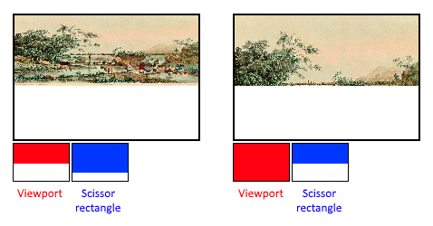
- 이 튜토리얼에서는 전체 프레임버퍼를 단순히 그리는것이 목적이므로
- 전체를 포괄하는 사각형으로 지정
VkRect2D scissor{};
scissor.offset = {0, 0};
scissor.extent = swapChainExtent;
- 이런 viewport와 scissor rectangle은 VkPipelineViewportStateCreateInfo 구조체를 통해 결합됨
- 몇몇 그래픽카드들은 여러개의 뷰포트와 siccor rectangle을 사용할 수 있으므로
- array 멤버를 참조해야함
- 이러한 다중기능을 사용하려면, GPU feature를 활성화해야함 (see logical device creation)
VkPipelineViewportStateCreateInfo viewportState{};
viewportState.sType = VK_STRUCTURE_TYPE_PIPELINE_VIEWPORT_STATE_CREATE_INFO;
viewportState.viewportCount = 1;
viewportState.pViewports = &viewport;
viewportState.scissorCount = 1;
viewportState.pScissors = &scissor;
4. Rasterizer
- rasterizer는 vertex shader의 vertex에 의해 형성되는 geometry를 가져와
- fragment shader에의해 착색될 fragments로 변환한다.
- 또한 depth testing, face culling and the scissor test를 수행하며,
- 폴리곤 전체를 채우거나 edge(wireframe rendering)를 출력하도록 구성할 수 있음
- 모든 설정은 VkPipelineRasterizationStateCreateInfo 을 통해서 수행함.
VkPipelineRasterizationStateCreateInfo rasterizer{};
rasterizer.sType = VK_STRUCTURE_TYPE_PIPELINE_RASTERIZATION_STATE_CREATE_INFO;
rasterizer.depthClampEnable = VK_FALSE;
- depthClampEnable 를 VK_TRUE 로 설정하면
- - - - near and far plan을 벗어난 이 파기되지 않고 clamped 되어
(전방절단면, 후방절단면)
- - - - shadow maps 같은 특별한 경우에 유용함
- - - - 이런 기능을 사용하려면 GPU feature를 활성화해야함
rasterizer.rasterizerDiscardEnable = VK_FALSE;- rasterizerDiscardEnable 를 VK_TRUE 로 설정하려면
- geometry는 절대 rasterizer stage를 통과하지 못함.
- 이는 기본적으로 framebuffer에 대한 모든 출력을 비활성화하는것이다.
rasterizer.polygonMode = VK_POLYGON_MODE_FILL;- polygonMode : 어떻게 fragments를 생성하는지에 대한 방법을 결정
- - - - 채우기 모드가 아니라 다른 모드를 사용하려면 GPU feature를 활성화 해야함
- VK_POLYGON_MODE_FILL: fill the area of the polygon with fragments
- VK_POLYGON_MODE_LINE: polygon edges are drawn as lines
- VK_POLYGON_MODE_POINT: polygon vertices are drawn as points
rasterizer.lineWidth = 1.0f;- lineWidth 멤버는 직관적으로, fragments 을 기준으로 선 두께를 나타냄
- 지원되는 최대 선폭은 하드웨어에 따라 다르며, 1.0f 보다 두꺼운 선은
- wideLines GPU feature를 활성화 해야함
rasterizer.cullMode = VK_CULL_MODE_BACK_BIT;
rasterizer.frontFace = VK_FRONT_FACE_CLOCKWISE;
- cullMode 변수는 the type of face culling 을 결정. ( disable culling, cull the front faces, cull the back faces or both)
- frontFace : 전면의 vertex 순서 를 결정함 (can be clockwise or counterclockwise.)
rasterizer.depthBiasEnable = VK_FALSE;
rasterizer.depthBiasConstantFactor = 0.0f; // Optional
rasterizer.depthBiasClamp = 0.0f; // Optional
rasterizer.depthBiasSlopeFactor = 0.0f; // Optional
- rasterizer 는 depth values을 변경할 수 있다.
- - - - (상수값을 추가하거나 fragment의 기울기에 따라 편향값을 변경하여)
- - - - shadow mapping에 사용되기도하지만, 여기선 사용하지 않으므로
- - - - depthBiasEnable를 VK_FALSE로 설정
5. Multisampling
- VkPipelineMultisampleStateCreateInfo
- anti-aliasing을 수행하는 방법중 하나인 멀티 샘플링을 구성하는 구조체
- 동일한 픽셀로 rasterize하는 여러 다각형(polygon)의 fragment shader results을 결합하여 작동
- 가장 눈에띄는 aliasing artifacts가 발생하는 가장자리에 따라 발생함.
- 하나의 다각형(polygon)에만 pixel에 매핑할 경우
- fragment shader를 여러번 실행할 필요가 없기 때문에,
- 단순히 고해상도로 렌더링한 다음 downscaling한것보다 훨씬 저렴함.
- 이를 사용하려면 GPU feature를 활성화해야함
VkPipelineMultisampleStateCreateInfo multisampling{};
multisampling.sType = VK_STRUCTURE_TYPE_PIPELINE_MULTISAMPLE_STATE_CREATE_INFO;
multisampling.sampleShadingEnable = VK_FALSE;
multisampling.rasterizationSamples = VK_SAMPLE_COUNT_1_BIT;
multisampling.minSampleShading = 1.0f; // Optional
multisampling.pSampleMask = nullptr; // Optional
multisampling.alphaToCoverageEnable = VK_FALSE; // Optional
multisampling.alphaToOneEnable = VK_FALSE; // Optional
- multisampling 챕터에서 다룸, 지금은 비활성화
6. Depth and stencil testing
- depth and/or stencil buffer를 사용할 경우, VkPipelineDepthStencilStateCreateInfo를 기술하여
- depth test 와 stencil test를 사용할 수 있음.
- 지금당장은 상요하지않기 때문에 struct 부분에 nullptr을 할당할것
- 해당 챕터에서 다룸
7. Color blending
- fragment shader 가 색을 반환한 다음
- framebuffer에 이미 존재하는 색들과 결합할 필요가 있음.
- 이 변환을 color blending이라고 하며
- 두가지 방법이 있음
- Mix the old and new value to produce a final color
- Combine the old and new value using a bitwise operation
- 기술해야하는 구조체는 두가지가 있다.
- VkPipelineColorBlendAttachmentState
- - - - 이 구조체는 연결된 프레임버퍼의 설정을 포함한다.
- - - - the configuration per attached framebuffer
- VkPipelineColorBlendStateCreateInfo
- - - - 이 구조체는 global color blending setting이 포함된다.
튜토리얼에서는 framebuffer를 오직 하나만 사용함.
7.1 PipelineColorBlendAttachmentState
VkPipelineColorBlendAttachmentState colorBlendAttachment{};
colorBlendAttachment.colorWriteMask = VK_COLOR_COMPONENT_R_BIT | VK_COLOR_COMPONENT_G_BIT | VK_COLOR_COMPONENT_B_BIT | VK_COLOR_COMPONENT_A_BIT;
colorBlendAttachment.blendEnable = VK_FALSE;
colorBlendAttachment.srcColorBlendFactor = VK_BLEND_FACTOR_ONE; // Optional
colorBlendAttachment.dstColorBlendFactor = VK_BLEND_FACTOR_ZERO; // Optional
colorBlendAttachment.colorBlendOp = VK_BLEND_OP_ADD; // Optional
colorBlendAttachment.srcAlphaBlendFactor = VK_BLEND_FACTOR_ONE; // Optional
colorBlendAttachment.dstAlphaBlendFactor = VK_BLEND_FACTOR_ZERO; // Optional
colorBlendAttachment.alphaBlendOp = VK_BLEND_OP_ADD; // Optional
- 이 per-framebuffer 구조체를 사용하면, color blending의 첫번째 방법을 구성할 수 있음.
- 수행될 작업은 다음 의사코드와 같음.
if (blendEnable) {
    finalColor.rgb = (srcColorBlendFactor * newColor.rgb) <colorBlendOp> (dstColorBlendFactor * oldColor.rgb);
    finalColor.a = (srcAlphaBlendFactor * newColor.a) <alphaBlendOp> (dstAlphaBlendFactor * oldColor.a);
} else {
    finalColor = newColor;
}

finalColor = finalColor & colorWriteMask;
- blendEnable 를 VK_FALSE로 설정하게되면 , 새로운 색은 수정되지 않은채 전달됨
- blendEnable 를 VK_TRUE로 설정하게되면, 두 색상을 혼합하여 새 색상을 계산함
- 결과색상은 colorWriteMask과 AND연산을 통해 어떤 채널이 실제로 전달되는지 결정함.
(위에 값은 r | g | b | a 로 모든 채널을 통과시킴)
- 가장 일반적인 color blending 방법은 alpha blending을 구현하는것
- 여기서 alpha blending은 불투명도를 기반으로 새 색상을 이전 색상과 혼합하려는것
finalColor.rgb = newAlpha * newColor + (1 - newAlpha) * oldColor;
finalColor.a = newAlpha.a;
- 이를 계산하려면 다음과 같이 위의 구조체를 수정해야함
- VK_TRUE로 설정해주고 BlendFactor를 수정해줘야한다.
colorBlendAttachment.blendEnable = VK_TRUE;
colorBlendAttachment.srcColorBlendFactor = VK_BLEND_FACTOR_SRC_ALPHA;
colorBlendAttachment.dstColorBlendFactor = VK_BLEND_FACTOR_ONE_MINUS_SRC_ALPHA;
colorBlendAttachment.colorBlendOp = VK_BLEND_OP_ADD;
colorBlendAttachment.srcAlphaBlendFactor = VK_BLEND_FACTOR_ONE;
colorBlendAttachment.dstAlphaBlendFactor = VK_BLEND_FACTOR_ZERO;
colorBlendAttachment.alphaBlendOp = VK_BLEND_OP_ADD;
- VkBlendFactor 와 VkBlendOp enumerations 에서 모든 연산을 찾을 수 있음.
7.2 VkPipelineColorBlendStateCreateInfo
- 두번째 구조체는 모든 프레임 버퍼에 대한 구조체 배열을 참조하며
- 앞에서 설명한 계산(aforementioned calculations)에서 blend factor로 사용할 수 있는
blend constants 를 설정할 수 있음.
VkPipelineColorBlendStateCreateInfo colorBlending{};
colorBlending.sType = VK_STRUCTURE_TYPE_PIPELINE_COLOR_BLEND_STATE_CREATE_INFO;
colorBlending.logicOpEnable = VK_FALSE;
colorBlending.logicOp = VK_LOGIC_OP_COPY; // Optional
colorBlending.attachmentCount = 1;
colorBlending.pAttachments = &colorBlendAttachment;
colorBlending.blendConstants[0] = 0.0f; // Optional
colorBlending.blendConstants[1] = 0.0f; // Optional
colorBlending.blendConstants[2] = 0.0f; // Optional
colorBlending.blendConstants[3] = 0.0f; // Optional
- 만일 두번째방법 (bitwise combination)을 사용하려면
- logicOpEnable 를 VK_TRUE로 설정해야함.
- bitwise operation은 logicOp 필드에 지정 가능
- 이것은 자동적으로 첫번째 방법을 비활성화함. (연결된 모든 프레임버퍼)
(Note that this will automatically disable the first method, as if you had set blendEnable to VK_FALSE for every attached framebuffer)
(colorBlendAttachment.blendEnable = VK_FALSE;로 설정한것처럼)
- colorBlendAttachment.colorWriteMask 또한 이 모드에서 실제로 영향을 받을 프레임 버퍼의 채널을 결정하는데 사용됨.
- 또한 두 모드 전부 비활성화하여 fragment colors이 수정되지 않게 framebuffer에 기록할 수 있음
8. Dynamic state
- 이전 구조체에서 지정한 상태의 제한된 양은 파이프 라인을 다시 만들지 않고, 실제로 변경할 수 있음
- ex) 뷰포트의 크기, 선 너비, 블렌드 상수 (size of the viewport, line width and blend)
- 이런 변수를 동적으로 변경하려면 VkPipelineDynamicStateCreateInfo 구조체를 기술해야함
VkDynamicState dynamicStates[] = {
    VK_DYNAMIC_STATE_VIEWPORT,
    VK_DYNAMIC_STATE_LINE_WIDTH
};

VkPipelineDynamicStateCreateInfo dynamicState{};
dynamicState.sType = VK_STRUCTURE_TYPE_PIPELINE_DYNAMIC_STATE_CREATE_INFO;
dynamicState.dynamicStateCount = 2;
dynamicState.pDynamicStates = dynamicStates;
- 이로인해 위에서 설정된 값들은 무시되며, drawing time때 이 데이터들을 명시할 필요가 있음
- 나중에 이 구조체를 다시 다룰것임.
- 동적 상태가 없음을 나타내기 위해 대신 nullptr를 파라미터로 넘길 수 있음.
9. Pipeline layout
- shader에서 uniform 값을 사용하여, dynamic state variables 과 유사하게
- drawing time에 shader의 동작을 변경하는 global shader를 사용할 수 있음
- 이들은 일반적으로 변환 행렬 (the transformation matrix)을 vertex shader로 넘길때 사용됨.
- 또는 fragment shader에서 texture sampler를 생성하는데 일반적으로 사용됨.
- VkPipelineLayout 객체를 만들어 파이프 라인을 만들때 이러한 uniform values를 지정해야함.
- 향후 챕터까지는 사용하지 않지만, 빈 pipeline layout을 만들 필요가 있음
- 이 객체를 class member에 만들어야함
- 나중에 다른 함수가 이 객체를 참조할것이기 때문.
VkPipelineLayout pipelineLayout;- 그 다음에 createinfo 구조체를 기술하여 상태를 기술해야함.
- createGraphicsPipeline 에서 이 객체를 생성해야한다.
VkPipelineLayoutCreateInfo pipelineLayoutInfo = {};
pipelineLayoutInfo.sType = VK_STRUCTURE_TYPE_PIPELINE_LAYOUT_CREATE_INFO;
pipelineLayoutInfo.setLayoutCount = 0; // Optional
pipelineLayoutInfo.pSetLayouts = nullptr; // Optional
pipelineLayoutInfo.pushConstantRangeCount = 0; // Optional
pipelineLayoutInfo.pPushConstantRanges = 0; // Optional

if (vkCreatePipelineLayout(device, &pipelineLayoutInfo, nullptr, &pipelineLayout) != VK_SUCCESS) {
    throw std::runtime_error("failed to create pipeline layout!");
}
- 이 구조체는 또한 push constants을 명시해야한다.
- push constants은 shader에 dynamic value를 넘길 다른 방법
- The pipeline layout 은 프로그램 전체에 걸쳐 참조될 수 있으므로 마지막에 제거해야함
void cleanup() {
    vkDestroyPipelineLayout(device, pipelineLayout, nullptr);
    ...
}
10. Conclusion
- 이 챕터의 모든 것은 fixed-function state 를 위한것이다.
- 이 모든것을 처음부터 세팅하는것은 많은 작업이지만
- 그래픽스 파이프라인의 과정을 거의 알수 있으므로 많은 도움이 된다.
- 이로인해 특정 components의 default state가 예상한것과 다르기 때문에
- 발생하는 unexpected behavior 의 가능성을 줄일 수 있음.
- render pass 객체를 만들고나면 이제 graphics pipeline를 생성할 수 있다.
전체 코드
C++ code / Vertex shader / Fragment shader
링크
https://vulkan-tutorial.tistory.com/19
https://m.blog.naver.com/PostView.naver?isHttpsRedirect=true&blogId=gomdev&logNo=220106219575
https://vulkan-tutorial.com/en/Drawing_a_triangle/Graphics_pipeline_basics/Fixed_functions
'그래픽스 > vk' 카테고리의 다른 글
| [vk] Drawing triangle - graphics pipeline basics - Conclusion (0) | 2021.08.09 |
|---|---|
| [vk] Drawing triangle - graphics pipeline basics - Render passes (0) | 2021.08.09 |
| [vk] Drawing triangle - graphics pipeline basics - Shader modules (0) | 2021.08.09 |
| [vk] Drawing triangle - graphics pipeline basics - introduction (0) | 2021.08.09 |
| [vk] Drawing triangle - Presentation - Image views (0) | 2021.08.09 |